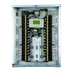
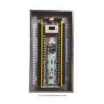
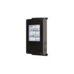
GR1416LT – LC&D 16 RELAY BLUE BOX LIGHTING CONTROL PANEL
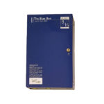
LC&D GR1416LT Blue Box Relay Panel
- Master Panel in Surface Mount Enclosure
- Modem not included
- Order Pre-Programmed for Easy No Hassle Installation (fees apply)
- 100% Digital 32 Channel Astronomical Time Clock
- Built-In Photocell Input on Board
- 16 Relays (included)
- Switching only (no dimming)
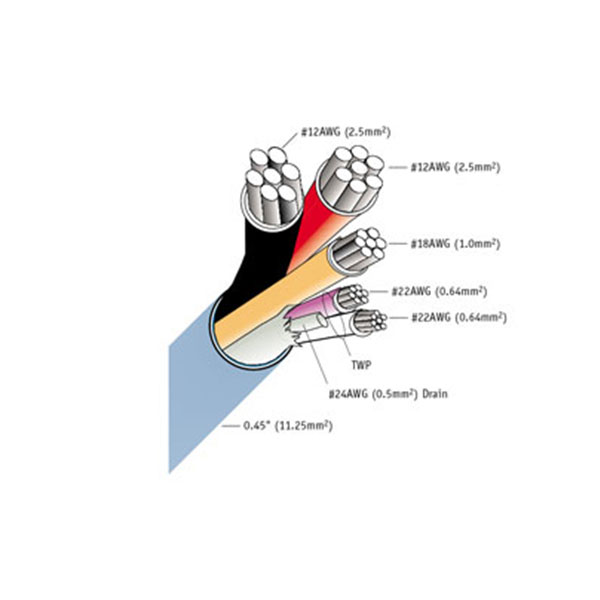
- Link Multiple Panels and Switches via Cat 5 Cable
- Connect Up to 16 Digital Devices
This is a complete basic system and does not include modem or other accessories. For custom options check out our customizer here.
For more information visit the Acuity website here.